5 potential fire hazards and mitigation in photovoltaic systems
PV systems prove themselves continuously as some of the most favored sources of alternative energy with more than 120 GW installed yearly in 2019. PV systems are extremely safe under normal operating conditions if installed and maintained by professionals according to electrical regulations and guidelines. However, with the increasing distribution of different PV systems operating both on the ground, rooftops and even integrated into buildings, the risk of a possible fire occurring where PV systems are installed has to be considered (as is the case with any electrical energy grid).
Between 1995 and 2012 in Germany, 400 fire cases were reported involving PV systems.
In 180 cases a single PV component was the source of the fire. To underline the safety of PV systems it must be mentioned that these 180 cases represented less than 0.1% of all fires in Germany during that period.
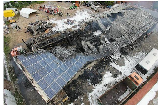
Fire in a factory in Norderney Germany, 8/2013. Damage cost totaling milions of euros (IEA)
Potential hazards of PV systems and mitigation
1. Combustion and pollution
Different components of a PV system are combustible due to their polymer content, for example: EVA encapsulation film and polymer back sheet in modules, polymers in string cables, junction boxes, and inverters. A research led by the German Federal Ministry of Economics and Technology identified that for a 9kWp system with 38 standard PV modules there is up to 60 kg of polymer material from modules alone. Polymers can produce an elevated temperature comparable to the temperature of heating oil (PE: 46 MJ/kg > heating oil: 43 MJ/kg)
During and after the fire, the PV system can potentially produce emissions in liquid, solid or smoke forms. The general public is safe from dangerous concentrations due to the low amount of hazardous substances existing in PV systems. However, firefighters responding to the incident could be exposed with dangerous levels of metals such as lead (c-Si) or cadmium and selenium if thin-film modules are present in the system.
Mitigation:
Firefighters must be informed about the existence of the PV modules as well as their location and type in order to plan their actions accordingly and safely.
Firefighters must use masks to protect themself from harmful and potentially toxic gas.
Debris from a damaged PV site requires professional disposal.
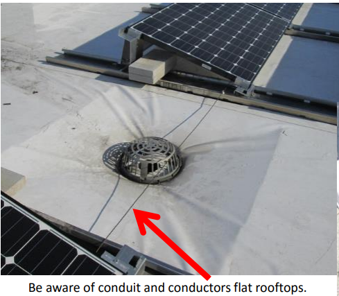
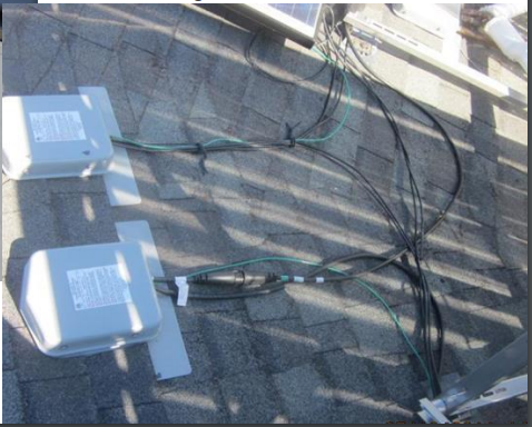
2. Slips and falls
Space limitation on the roof with PV system reduces the accessibility and may cause slips and/or falls.
Mitigation:
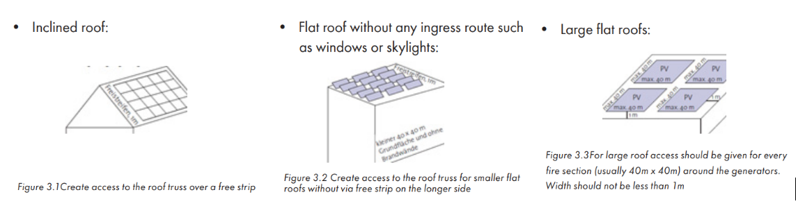
Preserve walkways with a certain width and setbacks from roof boundaries.
Label DC cables and keep an updated map of DC cable layout.
3. Collapse
PV equipment adds to the load on the roof, which can lead to a potential roof collapse. This hazard grows if the support beams are weakened during a fire. The modules could also fall during the fire, endangering both inhabitants and first responders.
Mitigation:
Be careful during the designing process and consult with the structural engineer if necessary.
Always inform firefighters of the presence of a PV system on the roof.
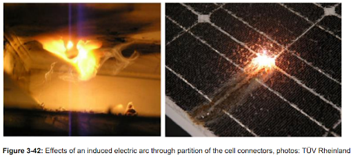
4. Arc or ground fault
PV systems have a high DC voltage which potentially creates a non-self-extinguish arc in case of a fault occurrence. The arc will continue until the voltage is turned off or the distance between arc contacts is increased.
The result for these arcs could be the poorly soldered cell connectors or soldering between cell connectors and the busbars inside the module.
Low-quality junction boxes with unstable cable connections and unsealed boxes can lead to corrosion, poor heat dissipation, low-quality bypass diodes also potentially resulting in an arc fault.
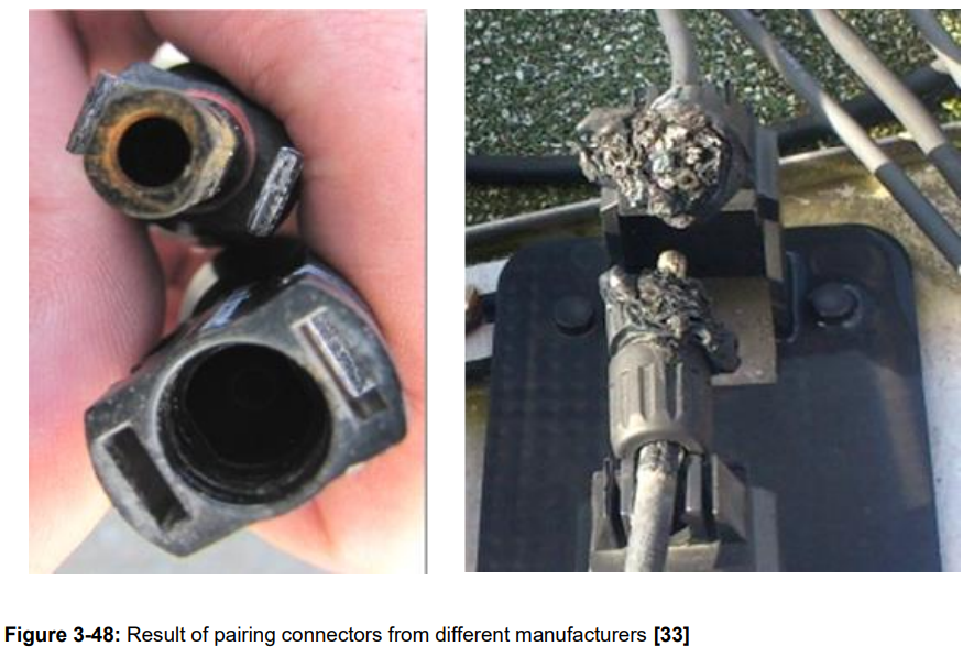
Another risk can arise when cross-mating connectors from two different manufacturers.
The electrical transition resistance may significantly increase, resulting in intense heating of the affected component.
Mitigation:
Choose only high-quality PV system components such as PV modules, cables, inverters. Check our post The List Of Tier 1 PV Manufacturers for further discussion about this topic.
Do not cross-mate connectors from different manufacturers.
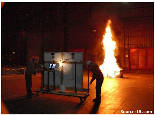
5. Electrical shock:
PV modules keep producing power as long as they are exposed to a sufficiently powerful light source. Even artificial light sources from halogen lamps can produce enough power to energize PV systems to a dangerous level. The same threat can come from light emanating from a nearby fire.
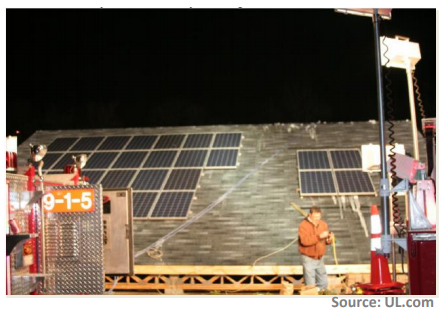
UL report of firefighter safety & Photovoltaic system (CESA
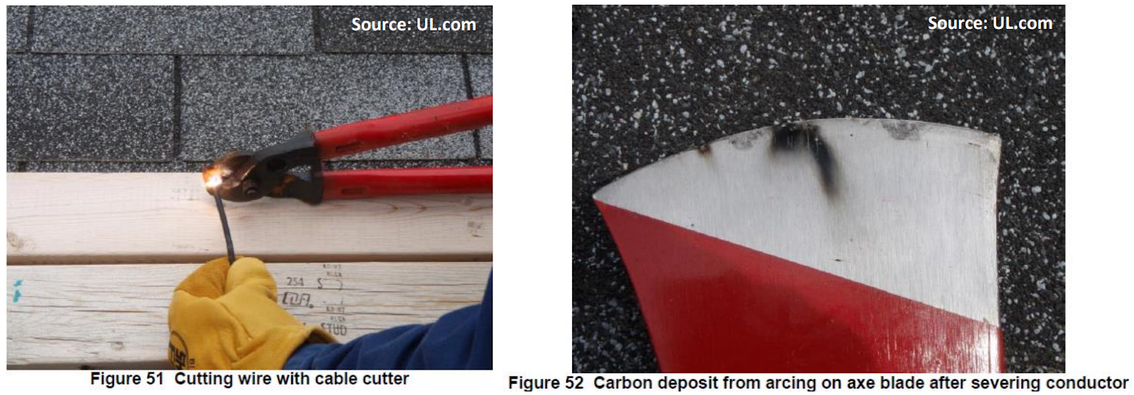
Another potential risk is if a firefighter must open the roof in order to access the PV system. This means cutting through live conductors, an action that almost always creates an arc and can constitute a significant and dangerous shock hazard.
Even damaged modules can still produce power which may harm firefighters and first responders during a containment operation. A test from UL shows that even after damage caused by heat or fire, 60% of the modules from the test site can still operate at full power.
Mitigation:
De-energize the PV system.
Firefighters must be equipped with a self-contained breathing apparatus.
Implement Rapid Shutdown solutions to eliminate firefighter exposure to the risk of direct contact with live DC cable.
Rapid Shutdown Solution:
In the United States, the National Electric Code NEC 2017 section NEC 690.12 requires DC voltage at module conductors to be lower than 80V within 30 seconds after rapid shutdown.
In Germany, the VDE-AR-E 2100-712 requires no more than 120 V throughout the PV array after shutdown.
With these following solutions installers can fulfill even the most strict standard.
Santon Firefighter safety switch (DFS)
This device can be installed near PV strings. In the case of a fire, when the firefighter switches off the AC circuit, Santon switch directly disconnects the DC current in close proximity to the solar modules which makes the place much safer for firefighters. The DFS will behave the same way if the temperature rises above 100˚C.
When AC power comes back on then the DFS device automatically switches on the DC power.
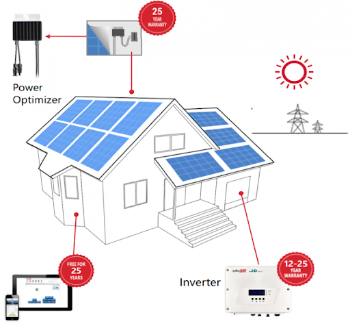
SolarEdge Solution
SolarEdge is among the very few solar equipment manufacturers which provide integrated rapid shutdown functionality. If one of the following methods is applied then string voltage will be reduced to the equal number of modules on a string (if 30 modules are in the string, then within 30s the string voltage is 30V):
The inverter AC breaker is turned OFF, or AC to the inverter is disconnected by another method (intentionally or as the result of a fault).
The inverter ON/OFF switch is turned OFF.
The DC switch is turned OFF (applicable only to inverters with a DC safety Unit).
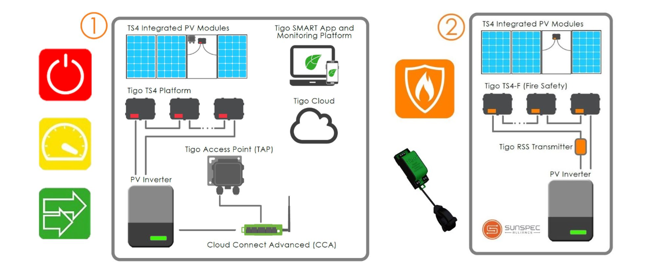
There are two ways to meet NEC 690.12 Rapid Shutdown requirements with Tigo.
Tigo’s Flex MLPE (Module Level Power Electronics) products use wireless communication between the TAP and TS4 module electronics. Flex MLPE requires a TAP and CCA (Cloud Connect Advanced) for a rapid shutdown.
The TS4‑F uses PLC communication and an RSS Transmitter. The TS4‑F does Rapid Shutdown only without module-level monitoring.
Both solutions can be applied to all major inverters and PV modules. In an emergency such as a fire, standard procedure for first responders is to disconnect the AC circuit breaker for the building. This loss of power from the grid causes the inverter and the Cloud Connect Advanced (CCA) or RSS Transmitter to turn off. Whenever the CCA or RSS Transmitter shut off, the TS4 units capable of safety (TS4-S, TS4-O, TS4-L and TS4-F) automatically enter module level disconnect mode and turn off output voltage and power completely. Thus, even if the emergency personnel do not activate the module level disconnect directly, the TS4 units are equipped to detect standard safety protocol and respond to the crisis. The same concept applies to a TS4-F based system. If external RSS transmitters are used, they need to be turned off at the same time as the inverter to meet NEC 690.12 requirements.
Check Tigo’s support for further information about Tigo’s solution.